Teleporting through Space across Time with Head-Mounted Displays
Companies, including Apple, Google, and Facebook, have invested significantly in AR/VR, e.g., a market research report states that AR/VR relevant investigation reaches 2.5 billion USD in 2017. We note that the definitions of AR, VR, and MR (Mixed Reality) are slightly different in different communities; we employ AR to refer to all the similar technologies. In this project, we aim to develop advanced AR communication systems, in order to capture, transmit, and render the indoor scenes to remote HMD viewers. Our goal is to deliver highly immersive viewing experience in on-demand manner, which allows HMD viewers to teleport through space and time.
Realizing teleportation is not an easy task, because existing 360-degree videos only offer 3 Degrees-of-Freedom (DoF), which are yaw, pitch, and roll, as illustrated at the left of Fig. 1. For immersive experience of teleporting to a remote site at different time, the AR communication system needs 6-DoF contents, where left/right (Y-axis), up/down (Z-axis), and forward/backward (X-axis) are also supported, so that HMD viewers may move within (e.g., walk through) the space at the remote site. A naive way to support 6-DoF is to capture 360-degree videos at multiple (too many) camera positions, and render the 360-degree video from the camera that is closet to the viewer’s current location. Doing so, however, would incur extremely high overhead and render the proposed solution impractical. To solve this issue, we study 3D scene reconstructions in this project, in order to support seamless 6-DoF viewing experience.

Goals and Overview
- Drone Swarms with A Lightweight Controller
- Coverage Path Planning of Drones
- SLAM Using Drone Markers
- Calibrating External Camera Matrix with Drone Swarms
- Integrating Sensor and Drone Data for 3D Reconstructions
- Scene Updates with 3D Grouping and Clustering
- Dynamic Application Deployment on Drones
- Point Cloud Coding with Auto-Encoders
- Prediction-based Foveated Rendering
Research Proposals
Drone Swarms with A Lightweight Controller
In the work, our main goal is to acquire the images (or other sensor data) of indoor scenes. These images 6 are later used to build 3D scenes. Nowadays, the common way to acquire images is done by hand: e.g., asking workers to shot photos one by one. A 360-degree camera may also be used to collect images of the whole room, which, however, may suffer from space distortion and blind spots. To eliminate these limitations, we need robots to replace humans for lower labor cost, while covering all the corners of each room. However, ground robots have difficulty to traverse through rooms that may have many furniture and obstacles, let alone go up/down stairs. In contrast, drones freely move in 3-D space and are more suitable for us. To quickly cover rooms of each house, we plan to build a drone swarm to systematically traverse through all corners and acquire images.

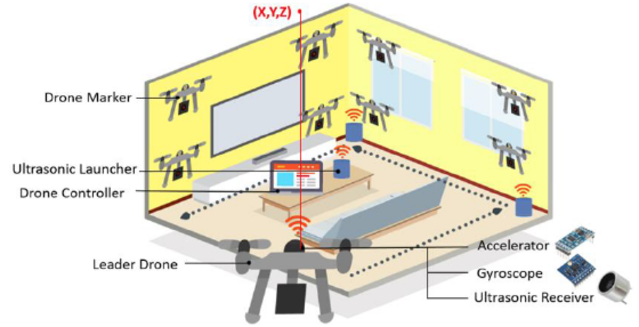
We will build a drone swarm system, which consists of: (i) a drone controller installed on a lightweight computer, e.g., a tablet computer (ii) multiple drones in the swarm, where one of them acts as the leader drone. Fig. 2 illustrates the considered scenario. The drone controller distributes the tasks among the drones, so that the image acquisition tasks are shared among all drones. The leader drone is responsible for more tasks, e.g., performing initial explorations or carrying heavier sensors (such as LiDars). However, existing studies fail to propose rigorous algorithms that work well when the rooms are full of furniture and obstacles. Moreover, the existing work often overlooks the computation resources on individual drones, and offloads all computations to a single server. In this project, we aim to perform some processing tasks among drones in a distributed way, instead of wasting these resources.
Coverage Path Planning of Drones
In this task, we minimize the total image collection time by generating the optimal flying paths for our drones. To achieve this, we first generate the camera positions, which include 3D coordinates and directions required by 3D reconstructions for collecting images. Those camera positions are calculated based on images collected by randomly moving tiny drones. Furthermore, we need to determine the positions of the flying drones, even although GPS does not work indoors.
For CPP problems, one naive way to cover all the required positions while considering the orientations of cameras is to rotate 360 degrees when arriving every position or use 360-degree camera to collect the images. However, rotating 360 degrees takes time, which results in very long image acquisition time. Moreover, using the 360-degree camera will increase the difficulty of 3D reconstruction because of the image shape distortion and insufficient resolutions. Hence, we plan to formulate the CPP problem as a mathematical optimization problem, which considers: (i) the overall distance while routing through all the positions, (ii) the orientations of cameras, (iii) flying directions, and (iv) rotation speeds. With the detailed formulation, we can leverage existing solvers, such as CPLEX to solve it. We may also use linear relaxation and rounding to design approximation algorithms and give approximation factors. For indoor localizations, ultrasonic sensors have high accuracy and consume little computation resources, but their signals are easily absorbed by furniture and obstacles. In addition, inertial sensors give positions in real time, need little computation resources, but suffer from accumulating errors. We plan to combine these two indoor localization techniques. Drones get their relative positions using inertial sensors, and calibrate their positions by ultrasonic sensors using ToA- or TDoA once in a while. Combining these two complementary technologies allows us to get accurate locations with fewer ultrasonic transmitters.
SLAM Using Drone Markers
Either in-situ sensors or floor-prints are assumed to be available thus far. Installing in-situ sensors may be too expensive, while building floor-prints may be incomplete. Hence, in this task, we would like to solve the image acquisition problem without any assumption on extra information. In particular, we plan to adopt Simultaneous Localization And Mapping (SLAM) algorithms on drones to automatically traverse through rooms and collect images. SLAM is an algorithm for robots to explore unknown environments by simultaneously estimating poses of robots and constructing the map.
Some work uses offloading mechanisms to run the complex algorithms on a workstation, which is a high-end computer to solve this problem. Other work does not employ workstations, but uses simple RGB cameras with pre-installed markers. However, simple RGB cameras do not provide depth information, which results in low SLAM accuracy. This is partially coped with the pre-installed makers; nevertheless, setting up the markers on walls, floors, ceilings, and furniture, is labor intensive. To address this limitation, we plan to leverage tiny drones to serve as markers. As illustrated in Fig. 2, we place the tiny drones (drone markers) right in front of the surfaces to serve as the markers.
Calibrating External Camera Matrix with Drone Swarms
In order to get fine-grained reconstructed scenes, the first step is to get the precise positions and poses of cameras across video frames. With accurate camera information, we then estimate the depth of each extracted feature, including feature points or surfaces. In this task, we first develop algorithms for: (i) leveraging pure visual data and (ii) fusing with depth cameras. We also discuss their limitations. We then employ programmable drone swarms with sensors to control camera movements for high-quality 3D reconstructions.

Our usage scenario is challenging for the state-of-the-art RGBD-SLAM, because:
- Texture-less environment: Different from the furnished indoor scenes, we aim to reconstruct rough-in houses, which contain texture-less plain painted wall. Due to the lack of references, the visual-based algorithms fail to track the camera positions. Fig. 3(a) shows an image frame from an empty conference room with extracted SIFT features marked in yellow.
- High-accuracy requirement: When viewing indoor real-estate (see Fig. 3(b)), it is important to produce accurate and detailed scenes. Take the door trim size as an example, it varies in the centimeter scale but has huge implications on insulation; and thus accurately preserving its dimension is crucial.
- Reflective material: Off-the-shelf depth cameras, such as Kinect and iPhone X TrueDepth, project structured lights in known patterns and estimate the depth by comparing the received patterns with the emitted ones. This limits its usability in real-estate scenarios, where reflected materials, including glass, iron frames, and translucent plastic sheets are everywhere. Fig. 3(c) is a sample frame from Kinect, which demonstrates that the depth camera fails to capture depth information on a monitor (rectangle in red) and then fail to understand the external camera matrix.
Integrating Sensor and Drone Data for 3D Reconstructions
We aim to estimate the 3D depth from 2D features such as points, lines, and planes. State-of-the-art 3D scene reconstructions fail to handle various real-world images and result in high computational overhead. We, therefore, propose integrating sensor and drone data into the reconstruction pipeline, in order to obtain indoor 3D scenes as accurate as possible. In particular, we obtain image and sensor data from the drones, along with their accurate coordinates in 3D world. There are three different 3D scene representations: the point clouds, 3D lines, and meshes. We choose mesh as our reconstruction format in order to remove outlier caused by inaccurate depth estimations, which is supported by several mesh-smoothing algorithms.
The state-of-the-art 3D reconstruction algorithms still suffer from the following limitations:
- Feature-less materials: In the MVS pipeline, we need to extract feature points from images in order to project them onto the epipolar line for depth estimation, but on some materials, e.g., glass, only a few feature points are found, and thus the reconstructed surfaces are un-smooth.
- Noisy sensor data: We obtain sensor data on the drones, including a depth map frame, inertial sensors, and locations. These sensor data are noisy and may result in inaccurate depth estimations.
Scene Updates with 3D Grouping and Clustering
We plan to support adding/removing objects (e.g., furniture) in the reconstructed scenes, which is referred to as updating scenes. As shown in Fig. 4, we divide this task into three parts: (i) 3D object segmentation and classification, (ii) 3D object removal/addition, and (iii) artifacts concealment. To support updating scenes, we have to know every object’s location, size, and shape. Such a task is known as 3D object segmentation. With surfaces in the reconstructed scenes, we add (or remove) objects, such as furniture, to (from) the scene. The last step of updating scenes is to eliminate the artifacts due to object removal. For example, after removing a chair, there might be some holes around the chair.

To add/remove the objects to/from scenes, there exist some challenges:
- Un-uniform density across the patches. Based on feature-based 3D reconstructions, the points are unevenly distributed. For example, the points on edges are denser than the points on flat surfaces.
- Point cloud data are unordered. A point cloud is a set of points without specific ordering. In other words, in order to train a 3D segmentation model invariant to input permutations, a network consumes n points needs to be invariant to n! permutations of the inputs in data feeding orders.
- Segmented surface shape can be arbitrary. After a series of geometric transformation, the shape of an object (i.e., a set of points) will be distorted, translated, or rotated. Rotated and translated points make object classification far more challenging.
- Missing surfaces are hard to concealment. Unlike in the 2D domain, the techniques of concealing the missing surfaces and artifact textures in 3D world remain open in the literature.
Dynamic Application Deployment on Drones
In our system, the main purpose of drones is data collection, by shooting photos (and collecting sensor data) at different locations for 3D scene reconstructions. To ease the burden of the server, drones also help with the data integration and analysis, e.g., by detecting and matching features among different photos and calibrating the cameras for image stitching. To achieve this, application modules for different purposes must be dynamically deployed on the drones. The applications include: (i) SIFT feature extractor, (ii) SIFT feature tracker, and (iii) image adjuster. However, the embedded devices are realized mostly in hardware for shorter response time and lower unit cost. Hence, they are less programmable.
There are several challenges when building such a platform. One of them is to build up a proper event-driven mechanism, which aims to automatically trigger the next module deployment after the previous one is done. This mechanism is essential to the platform since it should compose different modules into a complete request flow. With an optimized design, lots of manpower can be saved and the deployment efficiency can be improved. Another challenge is to build up a robust programming model, which is an algorithm to help us allocating and deploying the modules based on the resource usage of drones. The model is crucial for the efficient module deployment, and resource savings. The model needs to be carefully optimized for efficiency, considering the limited resources on drones. Furthermore, more complex requests need to be split into several modules, requiring greater degrees of flexibility.
Point Cloud Coding with Auto-Encoders
High-quality 3D point clouds require large storages. It is therefore difficult to directly transmit raw point clouds. Although many efforts are put in the standardization of point clouds, an efficient and intelligent compression algorithm for point clouds does not exist yet. Hence, an efficient compression algorithm for point clouds is needed. We propose a deep neural network (auto-encoder) to compress point clouds under diverse contexts. The auto-encoder is able to encode large point clouds to compact representations, which reduces the size of point clouds and also adapt to unseen objects. It effectively overcomes the difficulty of distinguishing two overlapping objects when operating interpolations with octree-based compression. However, it suffers from the following challenges: (i) real-time adaptive coding over constrained networks and (ii) realistic 3D reconstructions via generative adversarial training.

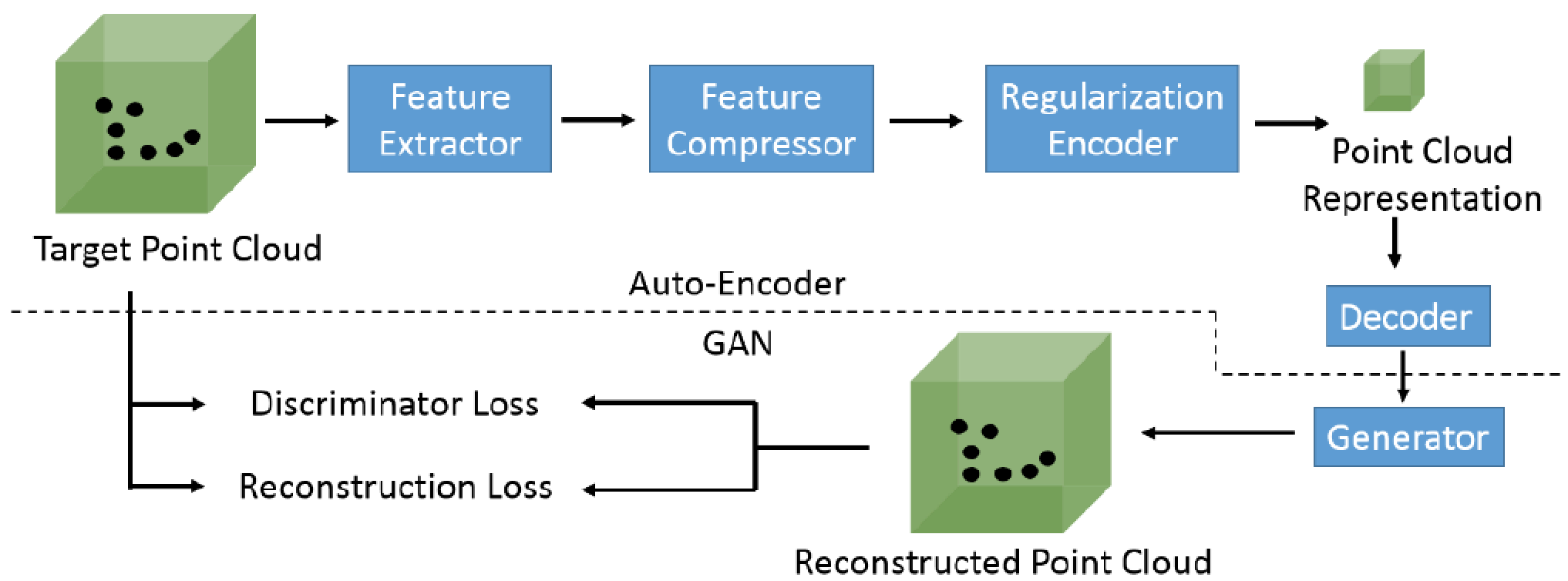
To address the above issues, we need an adaptive auto-encoder that generates long representations for complex 3D scenes and short for simple ones, while maintaining controllable sizes over diverse inputs. Fig. 5 shows our proposed auto-encoder, which includes the following components: (i) feature extractor, (ii) feature compressor, (iii) regularization encoder, and (iv) generator. The feature extractor is designed to recognize the diverse structures of the point clouds, including multi-scale point clouds. Next, the feature compressor compresses the extracted features to a fix-length representation. A regularization encoder is responsible to encode the compressed fixed-length representations into variable-length representations to fit the target bitrate. Besides, a generator is designed for further improving the similarity of the reconstructed and the target point clouds, according to the discriminator and reconstruction losses.
Prediction-based Foveated Rendering
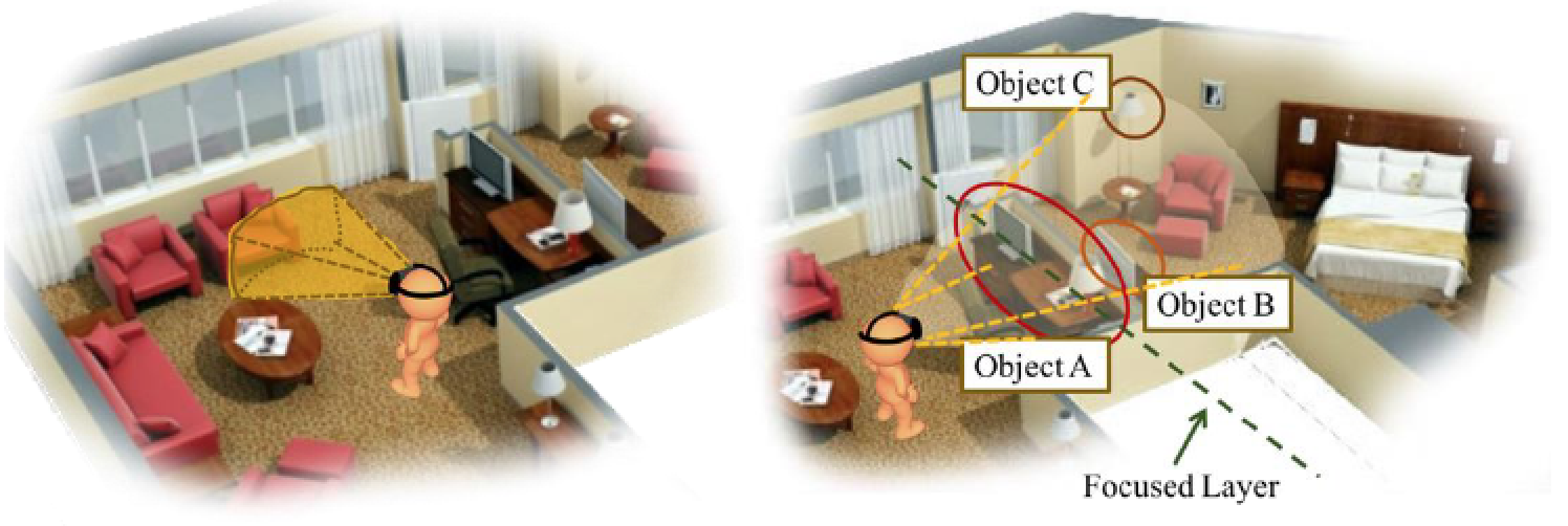
Rendering point cloud is challenging due to the extremely large data size. Such large data size leads to high loads on computation overhead for rendering. This may cause the inferior quality of reconstructed scenes and increase the difficulties on real-timeness. Existing studies propose to classify the 3D point clouds into objects, and construct a layered multi-resolution kd-tree to enable selective visualization on individual objects. In contrast, we propose to render the point clouds that are most likely to be viewed by the viewers. Fig. 6 shows that rendering the whole reconstructed scene actually wastes resources on unwatched parts and thus may degrade viewer experience. In this task, we propose to foveally render the 3D scenes based on viewport prediction.

Foveated rendering based on viewport prediction may run into the following challenges: (i) over-compressed content features for training and (ii) unknown user experience for foveated rendering. The number of saliency points in 3D scenes is far more than the content features in 2D 360-degree videos. However, reducing the size of 3D content features may result in information loss, and inferior prediction accuracy. On the other hand, foveated rendering involves proper configurations of size and quality of the foveal and peripheral regions. Larger foveal regions may lead to higher QoE, while reducing the system efficiency. The perceptual viewing quality and the trade-off between the quality and resource consumption on these regions are unknown. Furthermore, the same configuration may result in different QoE for different users. For example, some users may have larger foveal regions or are more sensitive to the quality drops among regions. Hence, it is challenging to achieve high user experience for all users.
